
A Frame Gantry Crane Lifting Mechanism Design Suggestion
Before design lifting mechanism of A frame gantry crane, you need to know what does A frame gantry crane lifting mechanism consist of? Generally, the lifting mechanism of A frame gantry crane includes driving mechanism, transform mechanism, winding system, fetching device, brake, and other safety device. Different types of gantry crane is equipped with different fetching device, the driving mechanism is also different. The layout of a typical lifting mechanism is shown in figure 1.
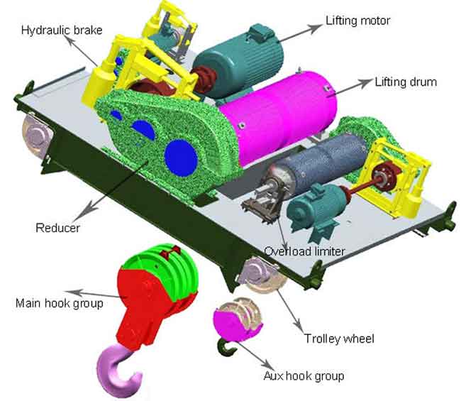
figure 1. lifting mechanism design of A frame gantry crane
main mechanism design in lifting mechanism of A frame gantry crane
When the lifting weight is more than 10t, two lifting mechanisms are often installed: main lifting mechanism (large weight) and secondary lifting mechanism (small lifting weight). Generally, the two mechanism works separately, but they may work together in some special cases. The lifting weight of secondary hook is usually 20% - 30% of the main hook lifting hook.
Driving mechanism
Most of the A frame gantry crane adopts motor drive, whose arrange, installation, and maintenance are convenient. Mobile crane (such as rubber tyred gantry crane and rail mounted gantry crane) is powered by a hydraulic device or an internal-combustion engine, the transform system is more complex than the control system.
Transform device
Transform device of A frame gantry crane includes reducer, coupling and transmission shaft. Reducer commonly used closed horizontal standard two or three cylindrical gear reducer, when the weight is large, sometimes a pair of open gear is added to obtain the low speed and big torque. In order to compensate the influence of the elastic deformation of the small frame after lifting the load on the reliability of the mechanism, the elastic pin coupling or gear coupling with compensation performance is usually used, some lifting mechanisms also employ a floating shaft (also called a compensating shaft) to increase compensation capacity, facilitate layout and reduce wear.
Winding system
The winding system of A frame gantry crane refers to the reel and wire rope pulley block. Bridge crane adopts double pulley block, single pulley block is generally used for jib cranes.
Fetching device
According to the different kinds and shapes of the materials being hoisted, adopt different kinds of fetching devices for the A frame gantry crane. There are a wide range of fetching devices, the most used is the hook.
N actuators and safety devices
The brake is not only the control device of the work, but also the safety device, so it is the key point of the safety check. The brake of the lifting mechanism must be normally closed. Motor driven cranes commonly adopts block brakes, the mobile crane adopts belt brake, and disc brake is adopted in recent years. Generally, the lifting mechanism of A frame gantry crane is designed with only one brake, which is usually mounted on a high speed shaft.
Difficulties when design lifting mechanism of A frame gantry crane
Lifting mechanism of A frame gantry crane is made up of spreader, reel, reducer, brake, motor and so on, the problems that may be difficult to handle in A frame gantry crane design are as follows:
The layout design of the reducer, motor, and reel on the A frame gantry crane
As if the distance among the three devices is changed, it will affect the selection of couplings and brakes.
Winding design of A frame gantry crane
Winding design is important when design the lifting mechanism of A frame gantry crane, the wall thickness of winding is depended on the maximum lifting capacity, the length of reel is determined by the diameter of the wire rope and the pitch of the drum. Only when the selection of the drum meets the design requirements can the speed of the output end of the reducer and the selection of the motor be determined according to the hoisting speed given, the output speed of the selected motor and the output speed of the reducer are used to determine the transmission ratio of the reducer, and a suitable type of reducer is selected.
Brake selection
The brake must be able to stop the motor output in time when the weight rises, stop the lifting mechanism while the heavy object moves horizontally, also stop in time for unloading to prevent damage to the goods. Therefore, the brake is an important safety device in the lifting mechanism, so it should be carefully chosen.
Checking the strength load of steel wire rope and reel
It includes internal force and strength of the main beam and the internal force of the leg.
Lifting mechanism design of A frame gantry crane
design specification:
| Lifting capacity | Q=40t |
|---|---|
| Lifting height | H=12m |
| Lifting speed | V=6.5m/min |
| Running speed of trolley | Vc=45m/min |
| Running speed of bridge | v=42m/min |
| Effective cantilever | Left: 8m; right: 8m |
| Working grade of whole crane | A5 |
| Working grade of mechanism | M5 |
Selection of slings for lifting loads
Adopt single hook form, according to the lifting capacity CP=40t, Working grade of mechanism is M32, choose M32 lifting hook. According to the selection of pulley block ratio of bridge crane, the ratio of pulley block can be chosen as 5m.
Suppose the weight of the pulley block and the hook is G=5T.
According to the selected pulley block, if the rigidity of the rope and the resistance of the pulley block are not taken into account, the static pulling force acting on the free end of the wire rope is taken as the static pulling force:
S=(Q/2m) * (1/η1η2η3η4)=(Q+G)/2m * (1/0.9)=(45/2*5)*(1/0.9)=5T
The free end of the wire rope is at a speed of:
V(rope) = m*VQ
Or VQ = V(rope)/m
Selection of wire rope

A steel wire is a thin wire of high strength, which is wound into a strand according to a certain pitch, and then twisted by a strand. The wire rope is divided into different parts according to its core material.
- Steel wire. The steel rope plays the role of loading, and its performance is mainly determined by steel wire. Steel wire is a kind of round (or special-shaped) wire made of carbon or alloy steel by cold drawn or cold rolling. It has high strength and toughness, treat the wire surface according to the use of different environmental conditions.
- Fiber core. It is used to increase the elasticity and toughness of the wire rope, to lubricate the copper wire, to reduce friction and to increase the service life. The commonly used rope core have organic fiber (such as hemp and cotton), synthetic fiber, asbestos core (high temperature) or soft metal materials, etc.
When used as lifting mechanism of medium and small sized crane, the fiber core wire rope can meet the demand of use in tensile strength and breaking force, and the A frame gantry crane needs winding when transporting material. Therefore, use fiber core wire rope, in order to increase service life, reduce the number of changes.
Diameter calculation of steel wire rope:
F0 ≥Sn
S: Maximum work static tension;
N: minimum safety factor.
Safety facto of working grade M5 is 5. Then F0≥Sn=50KN * 5=25KN
According to this to determine the structure of wire rope, so that to choose the clip wire rope, wire rope tie, collar, shackle.
winding drum design of A frame gantry crane
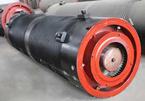
Wingding drum of the lifting mechanism is used for winding and storing lifting ropes. In the mass production of general medium and small A frame gantry cranes, the cast iron drums are usually made of single layer winding.
A spiral groove with an arc cross section is cut on the surface of a single winding drum to increase the contact area between the wire rope and the cylinder, and the wire rope is wound on the reel to avoid the friction between the adjacent wire ropes and the service life. According to the design requirement of A frame gantry crane, the single layer winding type wire rope casting drum is adopted.
After the wire rope is selected, the minimum limit size of the drum and pulley block can be derived from the following:
D ≥ e *d
D: The diameter of a drum or pulley (as the winding center of a winding wire rope)
e: times
d: diameter of wire rope
Here is the minimum allowable diameter of drums and pulleys. As for the determination of specific data, it is determined by various factors, and should be comprehensively considered from the overall arrangement of the organization and can be appropriately relaxed.
According to D ≥ e *d = 20*70=1400mm;
Select diameter of winding according to JB/T 9006.1-1999: 1800mm.
When the lifting height is H and the pulley block with multiplying m is used, the number of grooves on the reel with diameter of D (winding diameter) shall be as follows:
Z=(Hm/πV)+5
The steel rope is spirally wound on the reel, and the length of the spiral part of the rope groove shall be:
L = Zt mm;
t = d+(2~3)mm
t : screw pitch
Determine the length of the reel according to the calculation of the drum strength and the actual required winding.
Design and calculation of pulley
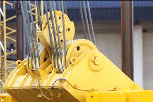
A rope pulley, usually used for guiding and supporting, to alter the direction of a rope and its transmission, or to balance the tension of a branch of a rope. As a labor-saving pulley block, the utility model can play the role of lifting heavy objects, or the free end of the flexible piece of the utility model or through the guiding pulley, or directly roll up the winch drum.
The pulley can be selected directly according to the pulley diameter and wire rope matching principle, and finally strength verification can be done.
motors design of A frame gantry crane
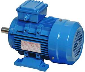
Special DC and AC motors are used in A frame gantry cranes in China. The main advantages of DC motor are its large speed range, high overload capacity, smooth speed regulation characteristics and larger starting and braking torque. The operating voltage is 220 V and 440 V. But there are some disadvantages, such as high equipment cost, large volume and the need for special power supply, a small number of metallurgical cranes and a large range of speed adjustment of the transmission mechanism, the use of DC motor.
The strength and rigidity of mechanism is designed big enough, thus the selection of motor is mainly the heat capacity selection of motor. Because the lifting mechanism belongs to the intermittent cycle work, the hoisting mechanism motor can be considered as the S3 work system. In A frame gantry crane, the three-phase AC induction motor and the conical rotor motor are generally adopted. The operating voltage is 220 V/, 380 V and 500V. According to the organization level, JZR2, YZR and JZRH type 3 phase alternating current motors are generally selected.
The advantages of cage induction motors are simple construction, easy operation, high slip, suitable for direct start and cheap price, the disadvantage is that the starting current is large (up to 4~6 times the rated current) and can not withstand more starting times. As the lifting mechanism, the motor needs to start frequently, so the cage motor is not suitable for selection.
Wire wound induction motors are the most widely used. Because the rotor circuit of the motor can be connected with the starting resistance to realize the starting speed regulation, the starting is stable, the starting current is usually no more than 2~215 times of the rated current, and the utility model has higher overload capacity. So we choose this kind of motor this time.
The static power of the motor is:
N=(QV/192η0)(KW)
η0: Total drive efficiency of hoisting mechanism
η1: pulley efficiency
η2: The efficiency of the guide pulley between the pulley block and the drum
η3:winding efficiency
η4: The efficiency of gear transmission from motor to winding
According to the static power of the mechanism, the motor with the corresponding JC% value can be selected. Because the winch does not work under rated load, and is also lower than the rated load power, moreover, the motor generally has a certain overload capacity, therefore, according to the catalogue of mechanical and electrical products, motors that are less than and near the static power can be selected.
Design and selection of reducer
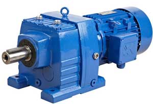
The reducer is an independent closed transmission between the prime mover and the operating machine, which is used to reduce the speed and increase the torque to meet the working requirements. In the design of the mechanism, the standard speed reducer supplied by the reducer manufacturer should be selected as much as possible. Reducer of A frame gantry crane is designed into ZQA type and QJ type of two categories, of which QJ is divided into two types with pedestal type and three pivot support type (below).
QJ series reducer has wide range of speed reduction, high mechanical transmission efficiency, stable operation, low noise, long service life, high carrying capacity, easy disassembly and inspection, easy installation. We choose the QJ series standard reducer in this A frame gantry crane design.
Brake design and selection of A frame gantry crane
The brake is an indispensable safety device for lifting mechanism, and it should be installed in the rigid connection between the high speed shaft and the drum.
General A frame gantry crane reducer is divided into disc and pad two types. Because the disc brake is to press the flat friction block on the brake disc in two directions to produce braking force, the braking friction force and the friction are damaged evenly, and the replacement is convenient, so the disc brake is selected here.
Coupling design and selection of A frame gantry crane
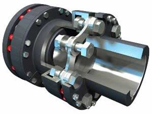
Coupling is used to connect two separate drive parts, such as the connection between the output shaft of the motor and the input shaft of the reducer, the connection between the output shaft of the reducer and the spool shaft, etc. For these couplings, there are two important additional requirements besides the ability to transmit torque:
- It is easy to install and can be disassembled without moving equipment;
- With certain radial, axial and angular compensation, because when the base of the mechanism is made wrong or deformed, it is necessary to make such compensation.
A plum shaped elastic coupling is used between the motor output shaft and the reducer high speed shaft. Because the motor output speed is high, with shock and vibration, this type of coupling has the function of damping vibration, in addition, it has the advantages of small rotary inertia and good compensation ability.
There is a greater torque between the lower speed shafts of the reducer, if use plain gear couplings, the dimensions will be great, therefore, we can choose the special toothed coupling for reel in recent years.

Gantry crane is a kind of deformation of the bridge type crane. It is mainly used for outdoor cargo yard, material yard cargo and bulk cargo handling operation....
Rubber tyred container gantry crane is a special gantry crane machinery used for container loading, unloading, handling. Use the lithium iron phosphate battery can solve the transfer problem of rubber tyred container gantry crane....
Compare rubber tyred gantry crane (RTG crane) and rail mounted gantry crane (RMG crane), there are five differences in technical performance, loading and unloading performance, operation performance, automation performance....